The model 214 Card Reader/Punch is an input/output device that uses full 12-punch codes. This implementation uses a window to represent the device. The device is a single-path punch card handler: Cards are taken from the input hopper, optionally read, optionally punched, and finally deposited at the output stacker. Punching a card, when no card was previously read, will cause a card to be loaded from the input and by-pass the reader.
The device is at the traditional address of 41/01. PDT instructions always operate on a full card, regardless of any RM in memory. However, transfer of characters stops at RM (or after column 80).
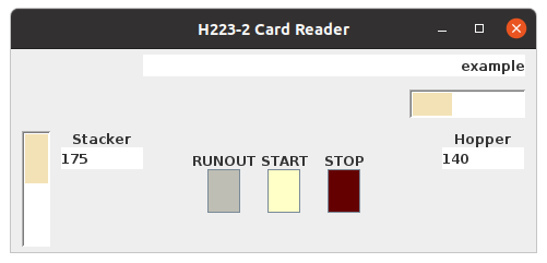
An optional configuration of an H223 Card Reader in addition to the H214 Card Reader/Punch may be selected with the property "readers=2". In this case, the H223 Reader is at address 41 and the H214 Reader/Punch is at 43/01. Note that the H223 hopper cannot be filled with BLANK cards, and the operator controls and hopper are arranged differently.
The device window is hidden by default. It may be made visible, and raised to the top, using the Front Panel menu "I/O" and selecting "PunchCard". If the optional second reader is configured, both windows are made visible. Closing the window only hides it, having no effect on the operation of the devices.
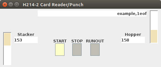
This device operates similar to the original equipment, in the sense that it will stall a PDT instruction if there are no cards in the input hopper. If a program wants to detect the end of a card desk, there must be a special card to indicate the end, such as "1EOFΔ", and the program must recognize the card and stop reading. There is a file "1eof.pcd" which contains one punch card with "1EOFΔ" which can be added to other decks as needed.
The window shows a picture of the input hopper on the right, and the output stacker on the left (cards move from right to left). The hopper/stacker operate in the standard fashion. Note that input file(s) are never altered, so discarding the output stacker after reading a deck of cards will not destroy the deck.
The number of cards in the input hopper and output stacker is shown, along with a visual representation of the respective card stacks. A red line on top of a stack indicates there are more cards than can be shown, however there are no physical limitations on the number of cards on the input hopper or output stacker - unlike original equipment.
The START, STOP, and RUNOUT buttons should behave similar to the original equipment. The RUNOUT button may be necessary under certain conditions to flush all cards through the device, especially when cards are being punched and the output stacker contents is to be saved.
NOTE: Punch cards are virtual objects in this implementation, and are not required to exist in only one place. Reading a deck of cards results in two copies existing, one in the original file and one in the output stacker. The same deck of cards may be loaded into the input hopper again without removing (the copy) from the output stacker, so repeated reading of a deck of cards (without clearing the stacker) results in multiple copies of the deck in the stacker. It will be necessary to keep track of the output stacker contents if you plan on saving it, or else unwanted card decks may be present in your saved file.
File format consists of two bytes representing each card column. The two bytes form a 16-bit word, where only the low-order 12 bits are used. These 12 bits are interpreted as the punch card zones, with bit 11 being zone 12, bit 10 being zone 11, bit 9 being zone 0, and so forth with bit 0 being zone 9.
The is also an application "CardPunch.jar" which may be used to create decks of cards, using an interface similar to original keypunch equipment.