The model 274 disk drives (any similar model controller) implements "random access" storage. This implementation uses a window to provide basic control for the 8 drives. The property "num_disk" may be used to configure less than 8 drives, with a minimum of 2.
The device control is at the traditional address of 04/44. Some details are lacking regarding various command specifics.
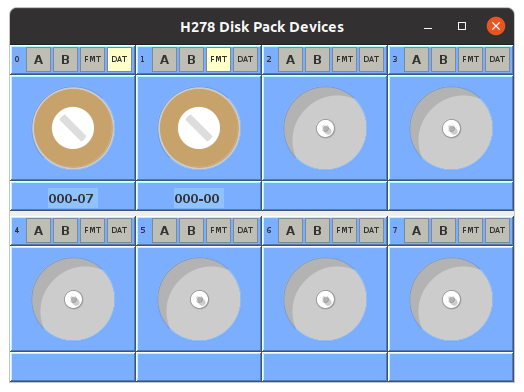
The Disks window is hidden by default. It may be made visible, and raised to the top, using the Front Panel menu "I/O" and selecting Disks. Closing the window only hides it, having no effect on the operation of the drives.
A full set of PERMIT buttons is provided for each drive: "A", "B", "FMT" (format), and "DAT" (data). The buttons toggle when clicked, illuminated means PERMIT writing. FMT allows formatting of tracks. DAT allows writing of data records on tracks. A and B allow finer-grained control over writing of records that were formatted with A/B flags.
Disk geometry is set as for Model 278 drives: 203 cylinders of 20 tracks (heads, surfaces) with 10400 raw characters per track. Each record consumes 11 additional characters to the record length. Raw capacity of a disk pack is 42 million characters. The image file format consists of 4060 blocks of 10000 bytes each, representing the tracks. The first 20 blocks (tracks) represent the first cylinder. Within a track, data is laid out starting with a 1-byte Address Mark followed by the header (FCCTTRRDL) followed by a 1-byte Data Mark, then DL bytes of data followed by either another Address Mark or an "end of track mark". Bytes from the End Mark to 10000th byte are ignored, although format commands can write there. The file size grows as tracks get formatted, with "non-existent" data effectively being "unformatted".
Each drive has a mount/unmount button that is depicted as the disk pack well. Clicking on the disk pack well opens a file dialog window for selecting the disk image to be mounted (clicking Cancel will leave no image mounted). Additionally, "FMT" and "DAT" buttons permit writing of track format and record data, respectively. In addition, "A" and "B" buttons exist to provide values to match against the A-File and B-File bits in record headers. These bits are treated as a mask, and "0" is always writeable (if "DAT" permit is on). So, if a record header has AB as "10", then that record can be written (only) if "A" is ON, but "B" may be ON or OFF (don't-care).
Active drives will show current head position/selection as Cylinder-Track, e.g. "000-06" for cylinder 0 head 6.
Due to lack of detailed information about these devices, the following has been assumed until more information is available:
| Command | Normal Termination | EXTENDED Termination |
|---|---|---|
| READ/WRITE | Record or RM | End of Track or RM |
| READ/WRITE INITIAL | Record or RM | End of Track or RM |
| SEARCH READ/WRITE | Record or RM | Error or RM* |
| SEARCH READ/WRITE NEXT | Record or RM* | Error or RM* |
NOTE: The documentation for the IBM 1401, often referenced by Honeywell as the target market for their computers, performed disk I/O using a buffer containing both disk address and data. However, since the H200/2000 series disk control units have a load/store address register command, it seems unlikely they would have included the disk address with the data.
The description of PDT for Disk Devices shows no method of selecting a disk drive (C3 is used for the command, and no other control characters are defined). The PCB instruction does define commands that select a drive, but only appear to select it for the duration of the operation. It is currently being assumed that the ADDRESS REGISTER "D" character selects the drive to be used for subsequent READ/WRITE operations. There can be only one data transfer active at a time, but multiple seek/restore operations on different drives could be active. The PCB instructions to test busy can select different drives, allow for multiple head-movement operations to be started and then polled to see what drive is ready to do I/O.
"Control Busy" is assumed to mean that the controller is performing an I/O transfer, between memory and the device selected by the "D" field in the address register.
"Device Busy" is assumed to mean that a device (drive) is performing a seek/restore operation OR an active I/O operation where that drive number is in the "D" field of the address register.
If "control allow" is ON and "control busy" transitions to not-busy, then a peripheral control EI is generated and the "control interrupt function" is turned ON.
If "drive allow" is ON and and drive's "device busy" transitions to not-busy, then a peripheral control EI is generated and the "device interrupt function" is turned ON. Unclear how to distinguish what drive completed, unless only one drive can be performing a seek/restore at a time. "Device busy" can be tested on each drive individually, and seek/restore can be initiated on each drive individually, but it appears that "device interrupt" is a combined status. Presumably, the OS must check all drives for "busy", combined with a list of ones which are (were) waiting, to determine which drive(s) are complete. Presumably, the "device interrupt" is not generated if only the transfer to that device completed, although it seems convenient to show the device busy while a transfer on that device is pending/active.